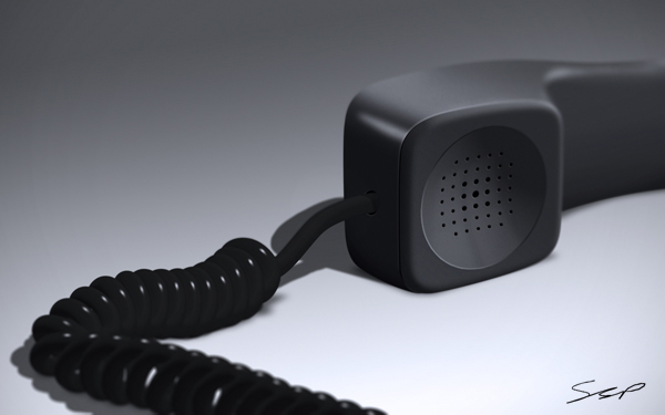
Final Product What You'll Be Creating
Given the right tools, Photoshop can make just about any task easy. Today’s tutorial will demonstrate how to create a still life telephone scene from scratch using the smudge tool. Let’s get started!
Step 1
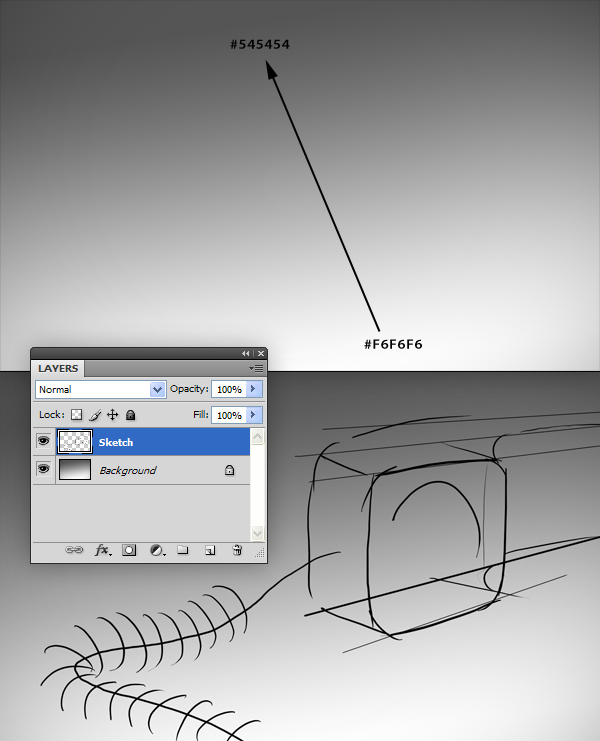
Create a new document (2100 px x 1300 px) and add a gradient as shown. Next, create a new layer called "Sketch" and draw a simple phone scene. It is important to rough out the path for the spring cord, as we will use this as a guide in the next step.
Step 2
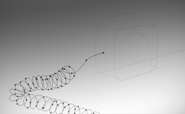
The first thing we’ll create is the spring cord for the phone. We’ll use a technique involving the Smudge Tool to do this. To begin, use the Pen Tool (P) to create a spiral path, using the sketch as a guide. Since we are just creating a path, it doesn’t matter which layer is selected. As you might tell, drawing a path this complex without any guides can easily produce some unrealistic results. Note: If your path goes off screen, it may ruin the effect. It is better to create a path completely within the canvas, and then move it to a desired location after step 5.
Step 3
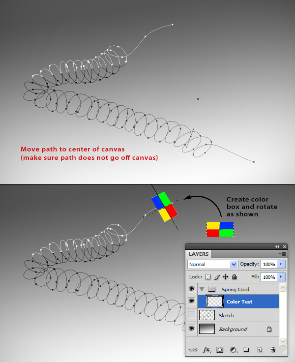
For this next effect to work properly, we need to move the path so that it is completely within the canvas.
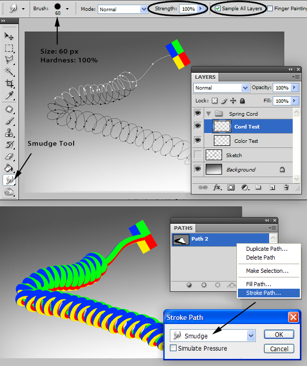
Now, before we create the actual cord, we are going to create a test cord so we can see how this technique works: Create a new group called “Spring Cord” with a layer inside called “Color Test.” On this layer, create a box and color it as shown. Rotate and position the box so that it is over the end point, perpendicular to the path.
Step 4
Create a new layer called “Cord Test” and select the Smudge Tool with the setting shown below. Now, go to the Paths Panel and select the path we created in step 2. Right Click and select Stroke Path using the Smudge Tool. As you can see, the colors from the box appear to be ‘extruded’ along the path. We can now use this color test to help us create the actual cord.
Step 5
On a new layer called “Shade Box”, create a new box (just like we did with the color test) and fill it with a light gray. Now that we know how the colors on the box are translated along the path, we can use the dodge and burn tools to add some shading to the gray box (feel free to experiment with different shadings). Now, create a new layer called “Cord” and, using the Paths Panel, add a Stroke Path just like we did in Step 4. The outcome is similar to a rail extrude effect seen in 3d software.
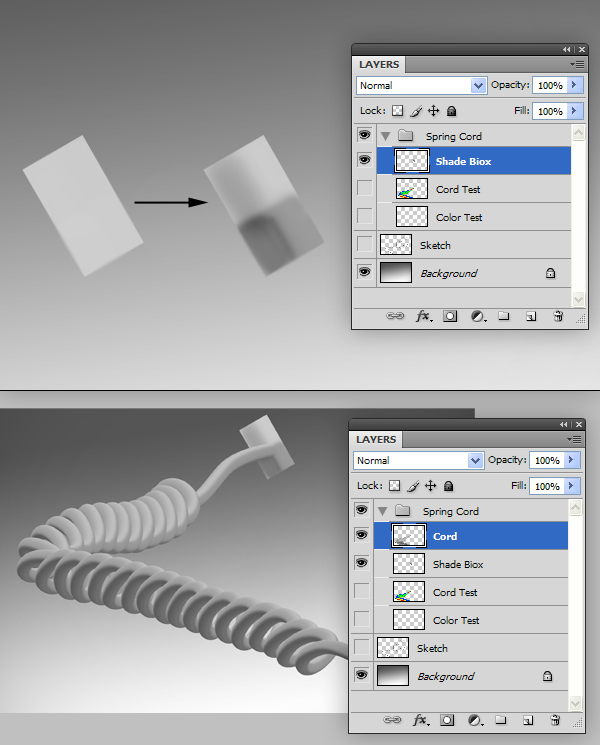
Now, move this cord back in to position according to our sketch.
Step 6
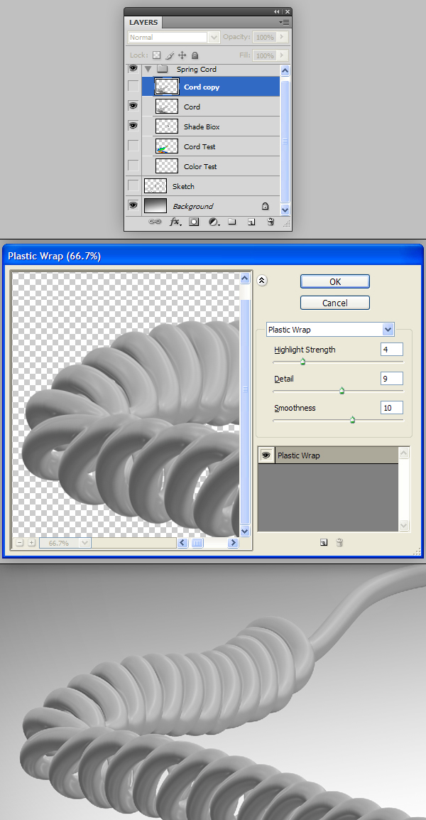
We now have the spring cord for our phone, but it looks a little flat. To fix this, make a copy (Cmd/Ctrl + J) of this layer and apply the Filter > Artistic > Plastic Wrap filter. The filter may produce some areas with undesirable results; simply use the Eraser Tool (E) to make these go away. When you’re finished, merge these two layers.
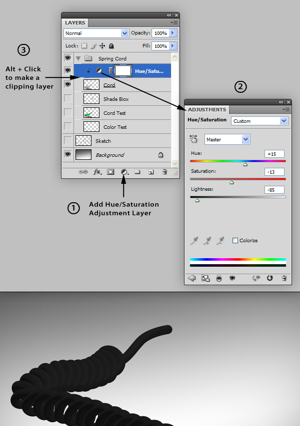
Step 7
With the merged “Cord” layer selected, add a new Hue/Saturation Adjustment Layer and make the adjustments as shown. Clip (Alt + Click) this layer to the “Cord” layer.
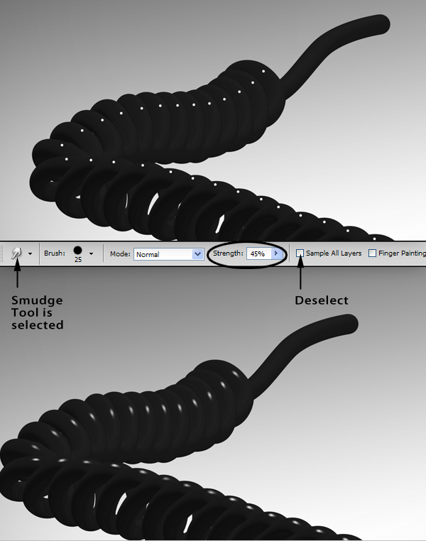
Step 8
On a new layer, use a small white brush to add dots to the top of each coil. Use the smudge tool with the settings shown to smudge each dot to resemble highlights. We are done with the cord. This technique can be used for many things, especially for creative typography.
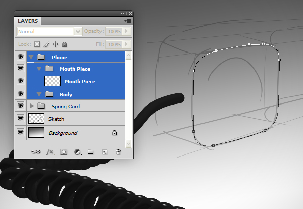
Step 9
Next, we’ll move on to the phone’s receiver, to start, create a group/layer hierarchy as shown. Use the Pen Tool to draw in the shape of the mouthpiece, with your sketch as a guide.
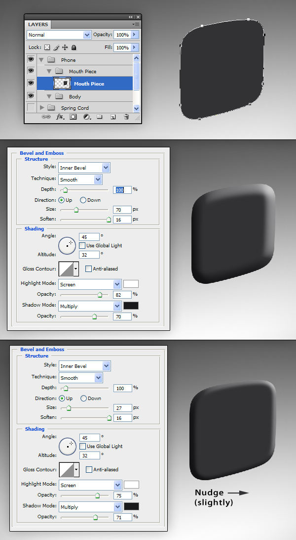
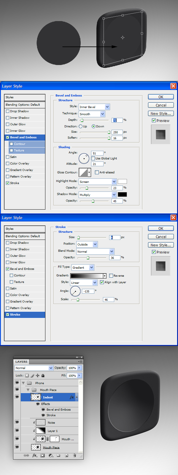
Step 10
On the "Mouth Piece" layer, select the mouthpiece path (from the Paths Panel) and fill with a dark gray. Now, we could dodge and burn this layer to add some 3D perspective, but instead, we’ll use another method. Start by adding a Bevel and Emboss to this layer. Next, make a copy (Cmd/Ctrl + J) of the layer "Mouth Piece" and decrease the amount of Bevel and Emboss. When you’re done, nudge the layer to offset it slightly.
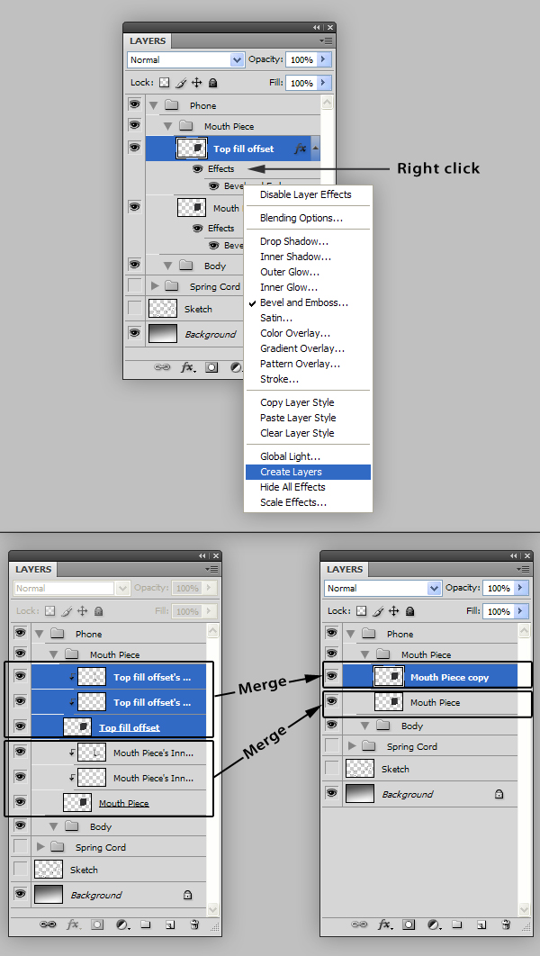
Step 11
Now, we want to merge the layer styles to their respective layers. To do this, right click on each layer’s "Effects" and select "Create Layers" from the dropdown to convert the layer styles into their own layers. Now merge the separated effects with their original layers.
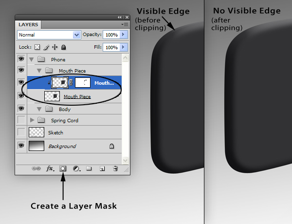
Step 12
Now we can clip (Alt + Click) the “Mouth Piece copy” layer to the one below. Add a layer mask to mask out the visible edges created by the two overlapping layers so it appears as one solid piece.
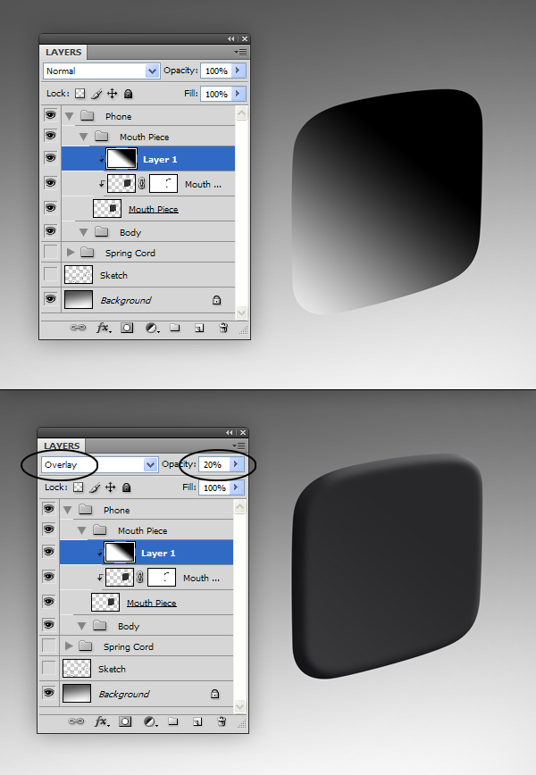
Step 13
Create a new layer and add a black-to-white gradient. Set the Blending Mode to Overlay and the Opacity to 20%. Clip this layer to the “Mouth Piece” layer.
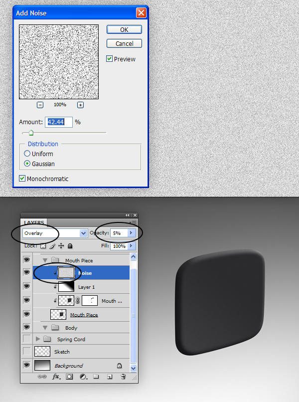
Step 14
Create a new layer called “Noise” and fill with white. Go to Filter > Noise > Add Noise, and use the following settings. Set the Blending Mode to Overlay and the Opacity to 5%. Clip this layer to the “Mouth Piece” layer.
Step 15
Create a new layer called "Indent." Use the Elliptical Marquee Tool to create a circle and fill it with a dark gray. Transform (Cmd/Ctrl + T) this layer to match the perspective of the mouthpiece. To make the indentation effect for the mouthpiece, add the following Layer Styles to the "Indent" layer.
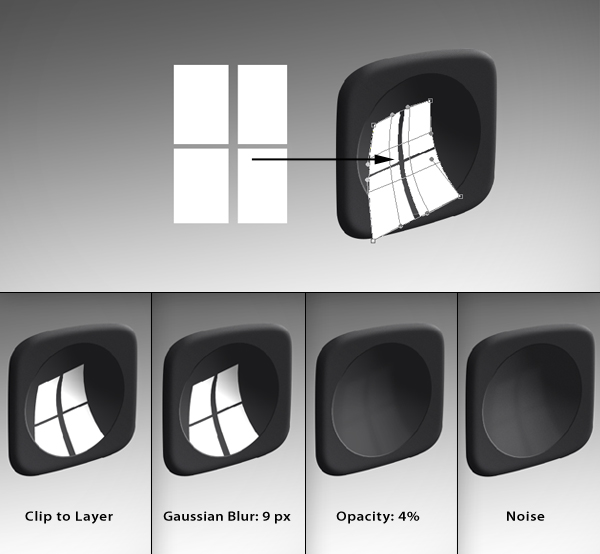
Step 16
On a new layer called “Highlight”, use the Rectangular Marquee Tool to create a shape similar to the one shown below and fill with white. Edit > Transform > Warp this layer to follow the indentation effect. Clip this to the “Indent” layer and give this layer a Gaussian Blur of 9.0 px and set its Opacity to 4%. Add a noise layer like we did in step 14.
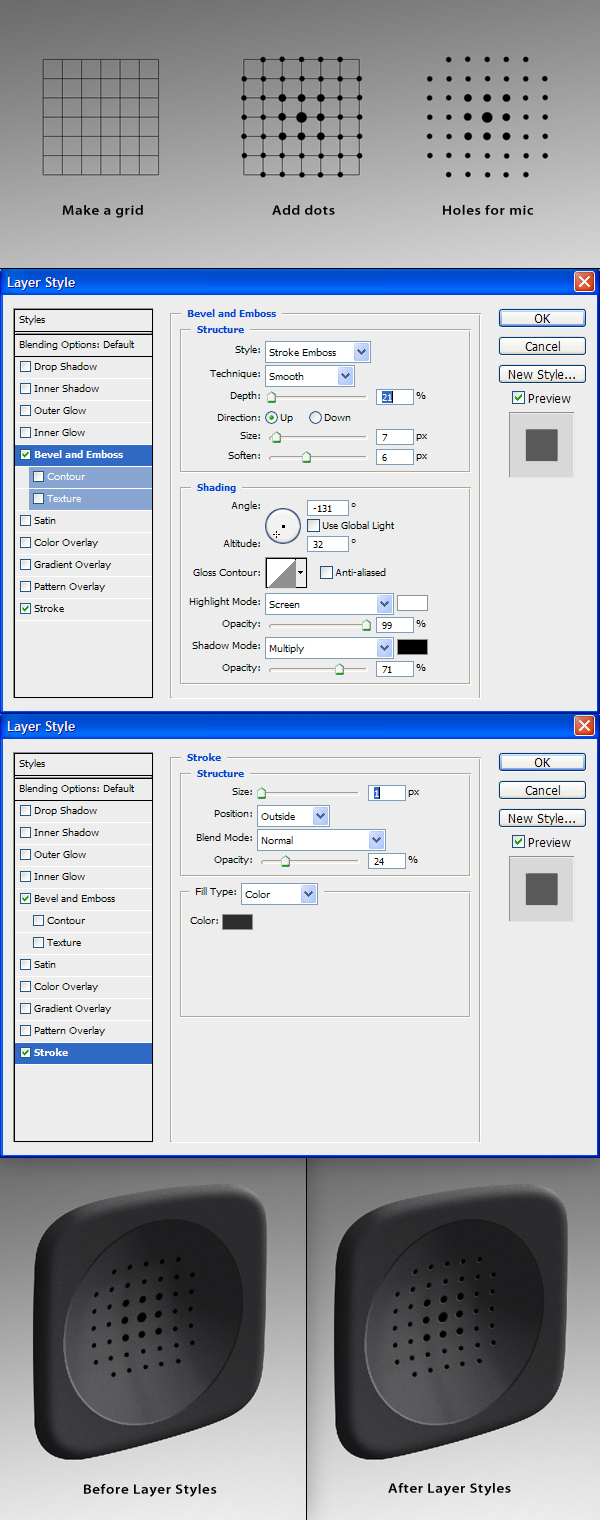
Step 17
To create the holes for the receiver, add a new layer called "Holes" and use a black brush to add dots with varying sizes in a grid pattern. It may help to create a template grid to guide you. Warp the dots just like we did with the "Highlights" layer and add the following Layer Styles to give depth to the holes.
Step 18
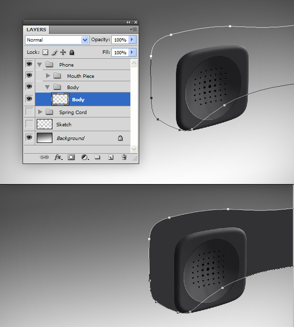
Now it’s time to move on to the rest of the phone. Create a layer called “Body” inside the “Body” group and use the Pen Tool (P) to draw the shape of the rest of the phone. Fill this shape with a dark gray.
Step 19
Since most of this phone will be blurred (which we will add later), we aren’t going to spend too much time adding detail. To begin, create a new layer called "Shading" and use the Brush Tool (B) to paint on some shadows and highlights by sampling the colors from the mouthpiece. Make this a clipping layer.
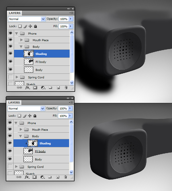
Step 20
Create a new layer called "Highlights". With a white brush, draw in highlights on the edges of the phone. Add a Gaussian Blur of 9.5%. Change the layer’s Blending Mode to Screen and its Opacity to 56%. Make this a clipping layer and add a noise layer (refer to step 14).

Step 21
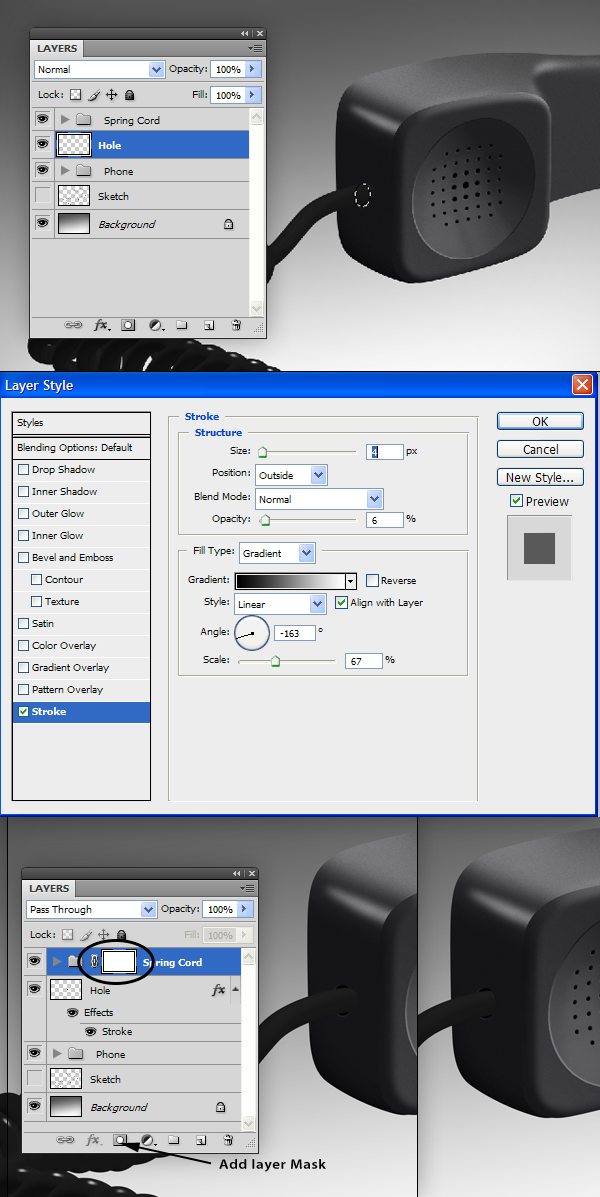
To make the cord appear to go into the phone, create a new layer called "Hole" in between the "Phone" and "Spring Cord" groups (make sure to move the "Spring Cord" group in front of the "Phone" group). Use the elliptical marquee tool to create an oval and fill with black. Add the following Layer Style. Add a layer mask to the "Spring Cord" group to mask out the end of the cord so that it appears to go inside the phone.
Step 22
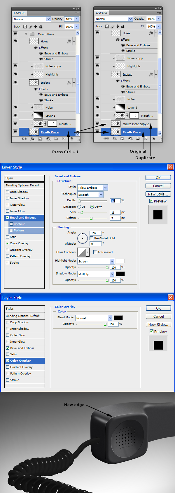
Looking at the phone again, I notice that the mouthpiece needs a little work on the edges where it meets the phone’s body. Go back in to the "Mouth Piece " group and find the "Mouth Piece" layer and duplicate it by pressing Cmd/Ctrl + J (this should preserve all of our clipping layers). Now, select the original "Mouth Piece" layer and add the following Layer Styles. Nudge this layer up and to the left until it looks good.
Step 23
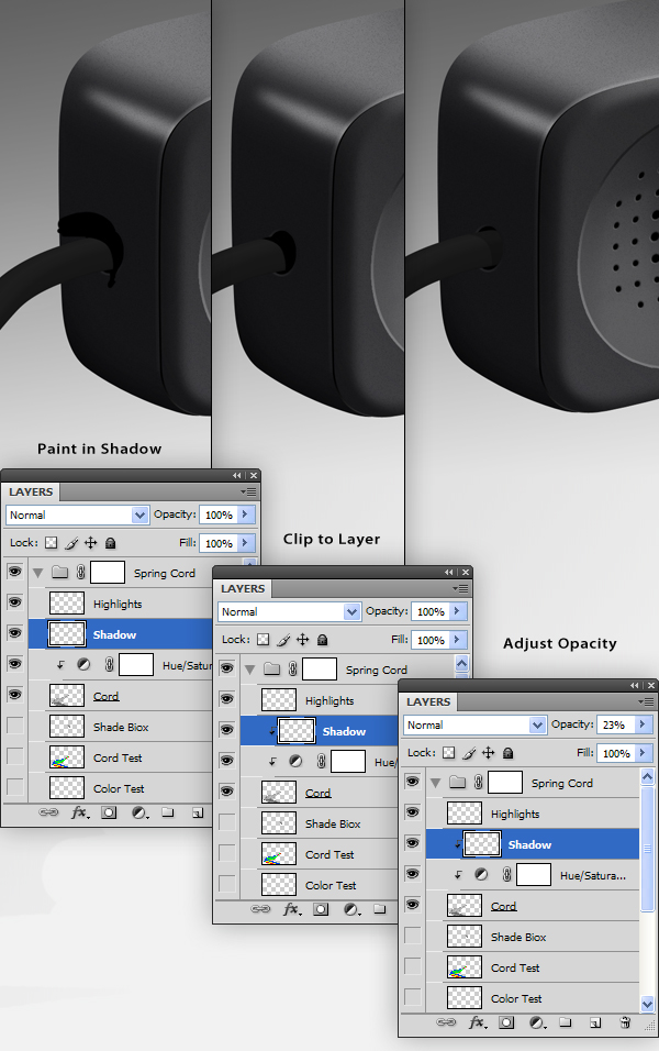
Now that the phone and cord are complete, we need to add some shadows. The first shadow will be on the cord where it enters in to the phone. Go back in to the "Spring Cord" group and create a new layer called "Shadow" above the Adjustment Layer. Use a black brush to paint in a shadow that the phone receiver would cast on the cord. Make this a clipping layer and adjust the opacity as necessary.
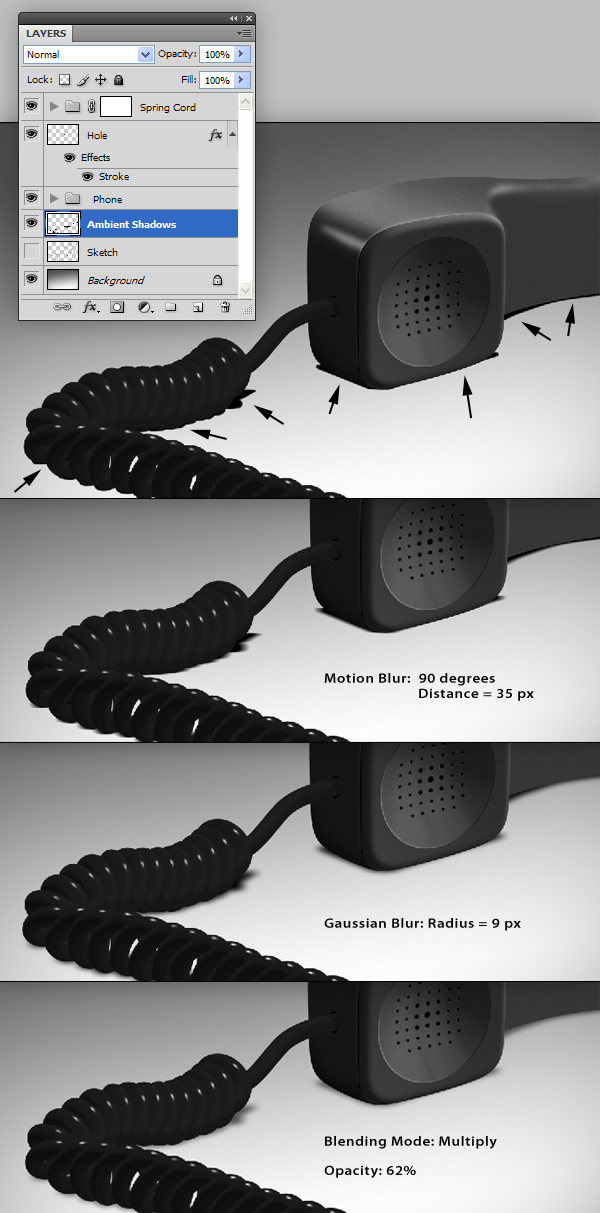
Step 24
Create a new layer called "Ambient Shadows" as shown. Using a black brush, paint in the areas where the spiral cord and the phone receiver may be in contact with the ground. Add a Filter > Blur > Motion Blur with a distance of 35 px at 90 degrees and then add a Gaussian Blur of 8.5 px. Set this layer’s Blending Mode to multiply and its Opacity to 62%.
Step 25
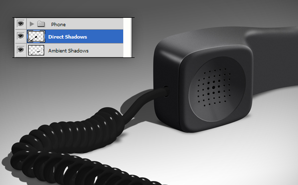
Create a new layer called “Direct Shadows” and paint in shadows that might be casted on the ground plane. Give this layer a subtle Gaussian Blur (1.0 px or less) and adjust the Blending Mode to Multiply and the Opacity to 63%.
Step 26
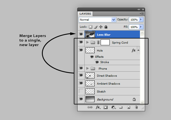
To finish the image, I want to add a depth-of-field effect. To do this, I am going to use the Lens Blur filter but, before we open it, we need to do some setup. Go ahead and merge the entire scene to a new layer and position it at the top of the stack and name it “Lens Blur”. This layer will be the layer that we apply the lens blur effect to.
Step 27
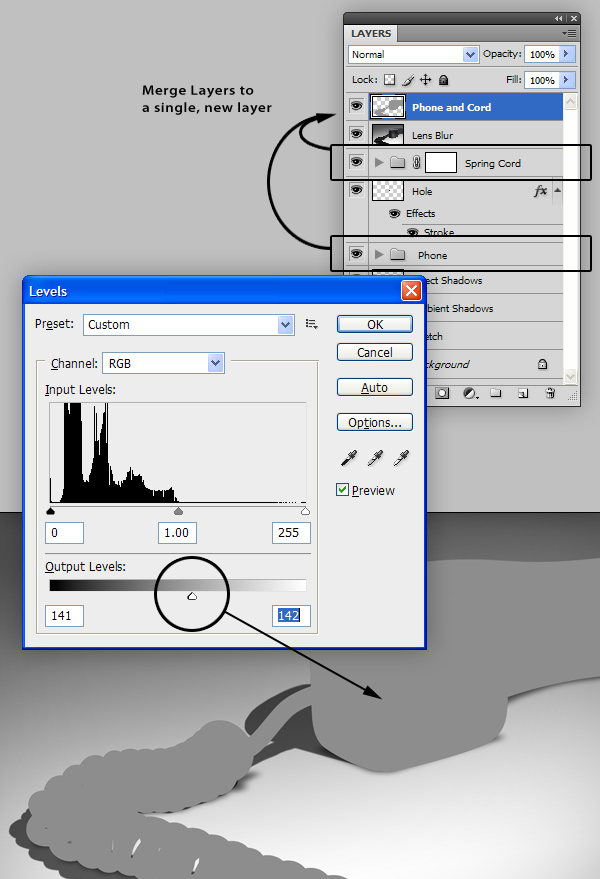
We want to make use of the Lens Blur filter’s ability to use a custom alpha map. To begin our alpha map, merge the “Phone” and “Spring Cord” groups together on a new layer called “Phone and Cord” and place at the top of the layer stack. Use the Levels (Cmd/Ctrl + L) to adjust this new layer to a medium gray.
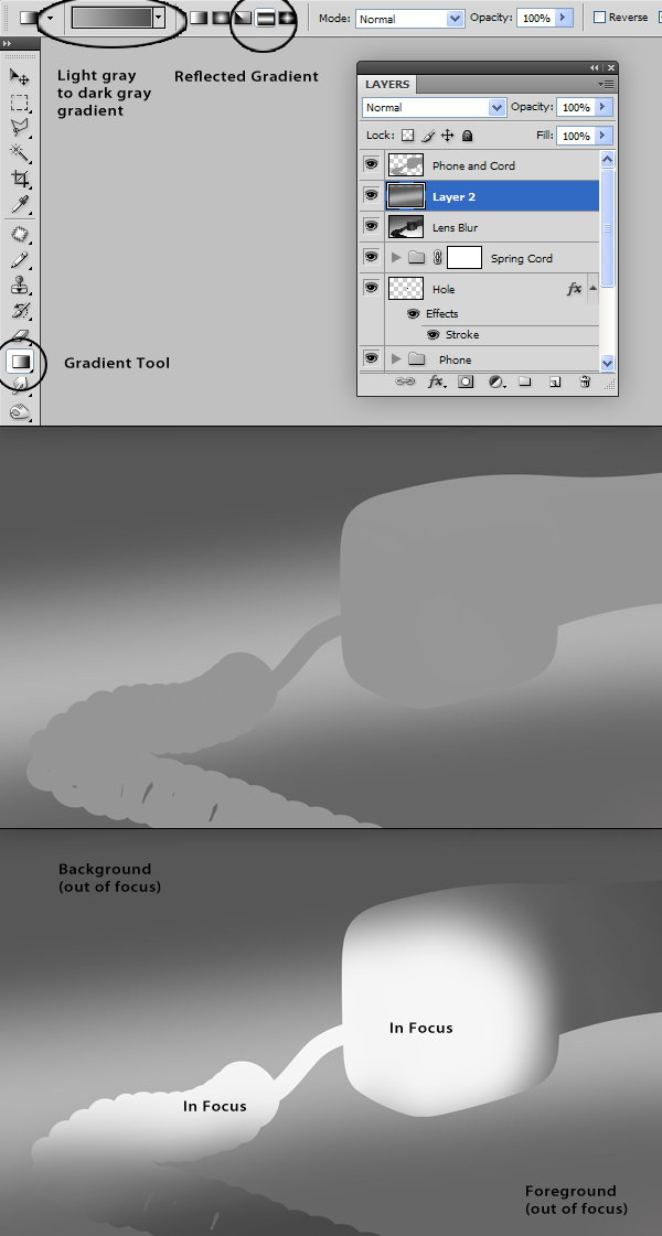
Step 28
Create a new layer above the “Lens Blur” layer and add a Reflected Gradient as shown. The lighter band will be the focal point for the Lens Blur effect. Therefore, the darker the color, the more the blur. Using this theory, we will apply whiter areas and darker areas to the “Phone and Cord” layer with the Dodge and Burn Tools.
Step 29
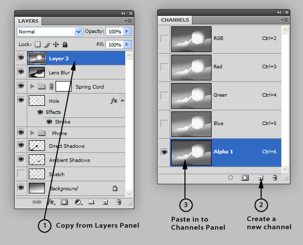
Merge the two layers we worked on and copy and paste this layer in to a new channel in the Channels Panel. This should automatically be named “Alpha 1.”
Step 30
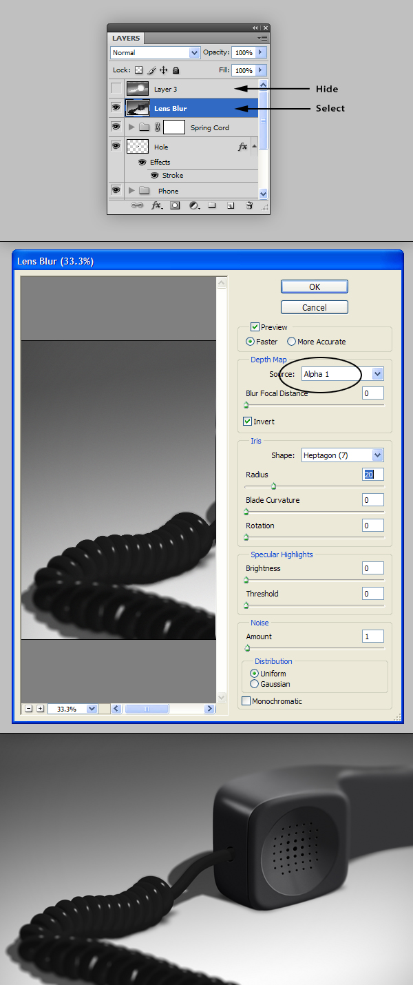
Hide the layer we were just working on and, with the “Lens Blur” layer selected, add Filter > Blur > Lens Blur with the following settings. This is where we will add our alpha map to influence the blur.
Conclusion
Make some tweaks if necessary. I gave the image a very subtle blue tint.


0 comments:
Post a Comment